Specification
|
Type
|
PC
|
|
Place of Origin
|
China
|
|
Zhejiang
|
|
|
Brand Name
|
SANYUE
|
|
Model Number
|
YSQ3-630/4P
|
|
Frame current
|
630
|
|
Product name
|
Automatic Transfer Switch
|
|
Pole
|
4P
|
|
Rated current
|
630A
|
|
Rated voltage
|
440V
|
|
Rated Frequency
|
50HZ
|
|
Control voltage
|
220V
|
|
Customized support
|
OEM/ODM
|
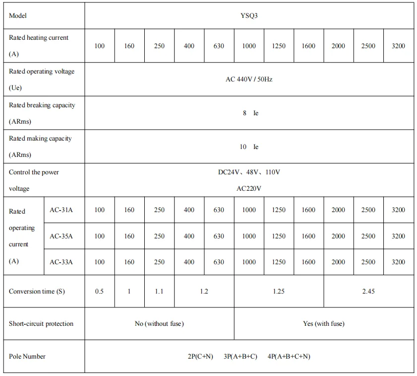
Main technical parameters
1. Conform to the standard: GB/T14048.11 / IEC60947-6
2. Conversion mode: Municipal electricity to municipal electricity, municipal electricity to generator
3. Function type: Automatic transfer and automatic recovery (If require automatic transfer without automatic transfer back, please specify)
4. Wiring method: Front-mounted wiring
Product model definition
|
Enterprise
Code
|
Product
Code
|
Shell
Current
|
Pole
Number
|
|||
|
YS
|
Q3
|
100
160
250
400
630
1000
1250
1600
2000
2500
3200
|
2P
3P
4P
|
With "F" indicates the fire type,that is the three-stage type:main power supply - double division - backup power supplyNo "F" indicates the two-stage type, that is the main power supply - backup power supply (Note: except 100A, the others are
two-stage and three-stage general purpose) |
"E" indicates 2 input and 1 output.The active and standby power supplies on the load side are connected together for easy
installation |
"Z" means intelligent, split controller: Y701 controller - over voltage, under voltage, phase loss, start generator and other
functions; Y702 controller - over voltage, under voltage,phase loss, start generator,485 communication and other functions. |
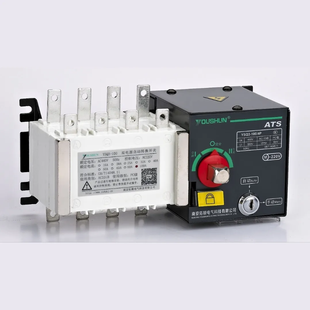
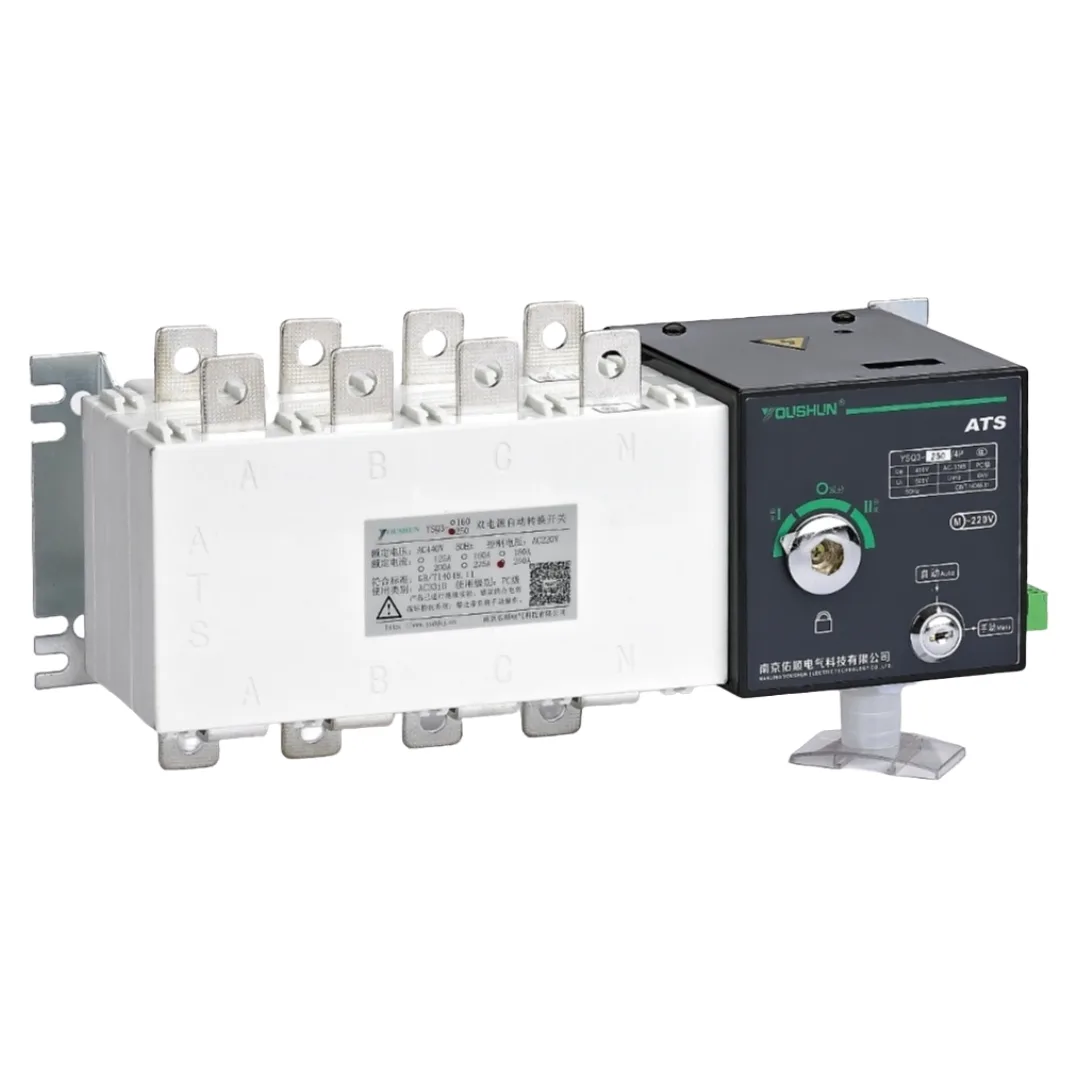
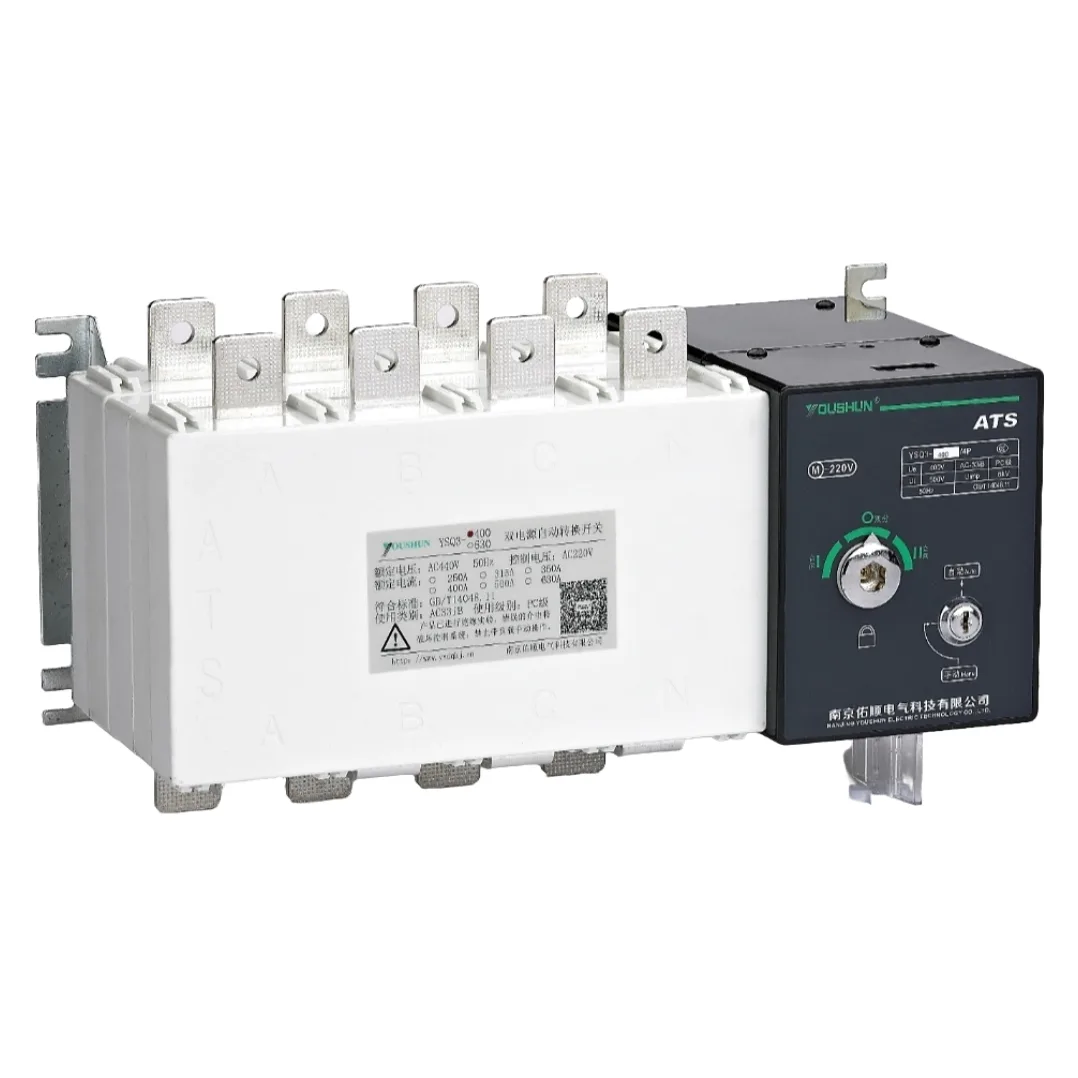
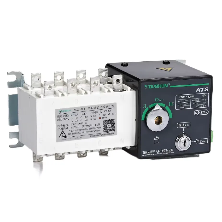
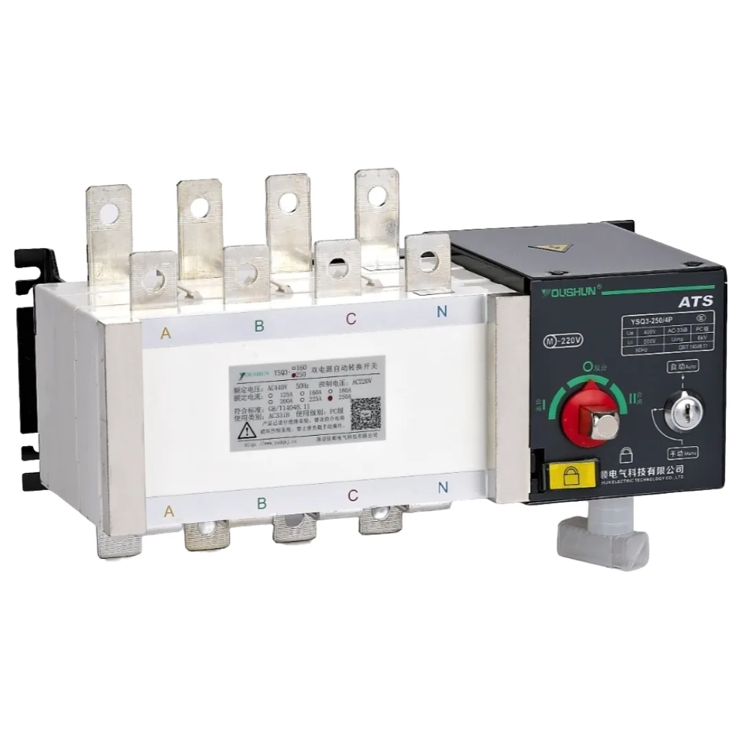
Switch structure description
1.Electrical key lock: Controls the power supply of the internal control circuit of the switch. When the electrical lock is on,
the switch can achieve automatic, remote control, and forced "0" operation. When the electrical lock is off, the switch can only be operated manually.
2.Operating handle: When operating manually with the operating handle, the electric lock must be closed first.
3.Institutional padlock: For maintenance purposes only. First, use the operating handle to set the switch to the "0" position,
then pick up the padlock mechanism and apply the padlock before conducting maintenance. (When the padlock is picked up, the internal control power of the switch is cut off, and the switch cannot operate automatically or manually.)
4.Indicator: Indicates the working status position (Ⅰ, 0, Ⅱ) of the switch.
Usage
(1) Switch Function
1.Fully automatic function: when the main power is cut off, the switch automatically converts to the standby power; when the main power is restored to normal, the switch automatically returns and converts back to the main power.
2.Force "0" function: Press the force "0" button and the switch will cut off the dual power supply.
3.Remote control function: That is for long-distance control. Press the "Ⅰ" gear button, the main power works; press the "Ⅱ" gear button, the standby power works; press the "0" gear button, both power circuits are cut off.
4.Please select the switch function as needed and connect the wires according to the corresponding function.
5.When placing an order, please specify the switch model, current specification and required functions.Letter and Symbol Explanations
1) C1 and N1 are respectively the fire line and neutral line of the common power supply, C2 and N2 are respectively the fire line and neutral line of the standby power supply. HL1 and HL2 are respectively the power indication of the common power supply and the standby power supply. HD1, HD2 and HD3 are respectively the indication of the input of the common power supply, the standby power supply and the fire protection (double division). FU1 and FU2 are 2A fuses.
2) Terminals 101-106 and 201-206 are for automatic conversion of secondary wiring.
3) Terminals 301 - 306 are for the external indicator lights of the automatic transfer switch.
4) In the fully automatic wiring mode, 201 and 206 must be short-circuited wiring.
5) Forced "0" contact (passive) also can input DC24V power.
6) K1 is the output of the power generation signal (when the main power is exhausted).
7) SA is the switch for choosing automatic/manual functions. SB1 and SB2 are respectively the manual input buttons for the main power supply and the standby power supply (passive contacts).